Extension for a Modbus RTU connection
The heat pump manager can communicate with external systems via the LWPM 410 extension, which is available as an accessory. The Modbus protocol, which is freely available on the market and can be implemented on other bus systems, serves as the interface protocol. It should be noted that over 100 variables can be transferred to the extension, which can be read out individually or transferred to a higher-level bus system.
| Table of Contents |
|---|
LWPM 410 extension 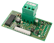 | |
Order reference | LWPM 410 |
item number | 339410 |
Device type | Slave |
protocol | RTU |
baud rate | 1200, 2400, 4800, 9600, 19200 |
Data format software version <L23 | 8N1 |
Data bits | 8th |
Parity | None |
Stop bits | 1 |
Data format software version> L23 | 8N1, 8N2, 8O1, 8O2, 8E1, 8E2 |
Data bits | 8th |
Parity | None, Even, Odd |
Stop bits | 1, 2 |
Network address | 1 ... 207 |
interface | RS485 |
Cable sizing | 2 x 0.5 mm² shielded |
Connection type | Screw terminals |
System requirement
The minimum system requirement for using the LWPM 410 extension is a Dimplex heat pump with heat pump manager WPM 2006, WPM 2007 or WPM EconPlus with software version H_H50 and higher.
Modbus / RTU
The Modbus protocol is a communication protocol based on the master / slave principle. A master device controls and monitors the entire data transmission in the network / bus system, the connected slave devices only respond when requested. The Dimplex heat pump manager can process the Modbus protocol in RTU mode.
Function codes supported
Type | R / W | Function code | Modbus function |
|---|---|---|---|
Digital | R. | 01 (0x01) | Read coils |
Digital | R. | 02 (0x02) | Read Discrete Inputs |
Analogue | R. | 03 (0x03) | Read Holding Register |
Analogue | R. | 04 (0x04) | Read input register |
Digital | W. | 05 (0x05) | Write single coil |
Analogue | W. | 06 (0x06) | Write single register |
installation
| Note |
|---|
ATTENTION |
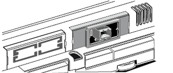
The installation of the LWPM 410 extension takes place on the heat pump manager in the designated slot “Serial Card / BMS Card”. The following steps are carried out:
De-energize the heat pump manager
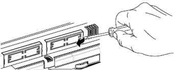
Remove the cover of the “Serial Card / BMS Card” slot with a small screwdriver
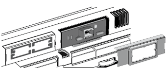
Installation of the LWPM extension
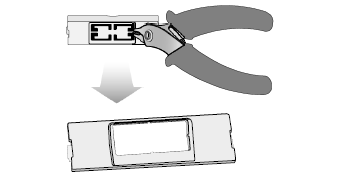
Breaking out the existing cover
Close the opening with the enclosed cover
Supply the heat pump manager with voltage
Heat pump manager settings
Depending on the software version on the heat pump manager, the following settings must be checked and adjusted if necessary:
from WPM_H with the key combinations «menu" and "Enter » in the "Modem" settings
from WPM_L with the key «menu»In the" Network "settings
Protocol: Modbus
Baud rate: 9600 -> factory setting, adapt to the network if necessary
Address: 001 -> factory setting, if necessary adapt to the end devices in the network
from WPM_L20.2 with the key «menu»In the" Network "settings
Protocol: Modbus
Baud rate: 9600 -> factory setting, adapt to the network if necessary
Address: 001 -> factory setting, if necessary adapt to the end devices in the network
Address range: 1..127 -> absolutely required
Data point list
Operating data
KNX / EIB | |||||||||||
|---|---|---|---|---|---|---|---|---|---|---|---|
Modbus | Modbus | Modbus | |||||||||
Address | Datapoint type | IN / OUT | COIL / REG | Conversion Rule | Conversion Value | DPT | Datapoint type | R / W | Unit | ||
Surname | WPM software J / L | WPM software H | |||||||||
Outside temperature (R1) | 1 | 27 | 16 bit float | OUT | register | None | 9.001 | signed 16 bit | R. | ° C | |
Return temperature (R2) | 2 | 29 | 16 bit float | OUT | register | None | 9.001 | signed 16 bit | R. | ° C | |
Return temperature setpoint | 53 | 28 | 16 bit float | OUT | register | None | 9.001 | signed 16 bit | R. | ° C | |
Hot water temperature (R3) | 3 | 30th | 16 bit float | OUT | register | None | 9.001 | signed 16 bit | R. | ° C | |
Set hot water temperature | 58 | 40 | 16 bit float | OUT | register | None | 9.001 | signed 16 bit | R. | ° C | |
Flow temperature (R9) | 5 | 31 | 16 bit float | OUT | register | None | 9.001 | signed 16 bit | R. | ° C | |
Heat source inlet temperature (R24) * | 6th | - | 16 bit float | OUT | register | None | 9.001 | signed 16 bit | R. | ° C | |
Heat source outlet temperature (R6) | 7th | 41 | 16 bit float | OUT | register | None | 9.001 | signed 16 bit | R. | ° C | |
Target temperature 2nd heating circuit | 54 | 32 | 16 bit float | OUT | register | None | 9.001 | signed 16 bit | R. | ° C | |
Temperature 2nd heating circuit (R5) | 9 | 33 | 16 bit float | OUT | register | None | 9.001 | signed 16 bit | R. | ° C | |
Target temperature 3rd heating circuit | 55 | 34 | 16 bit float | OUT | register | None | 9.001 | signed 16 bit | R. | ° C | |
Temperature 3rd heating circuit (R13) | 10 | 35 | 16 bit float | OUT | register | None | 9.001 | signed 16 bit | R. | ° C | |
Room temperature 1 / RT-RTH Econ | 11th | 36 | 16 bit float | OUT | register | None | 9.001 | signed 16 bit | R. | ° C | |
Room temperature 2 | 12th | 38 | 16 bit float | OUT | register | None | 9.001 | signed 16 bit | R. | ° C | |
Room humidity 1 / RT-RTH Econ | 13th | 37 | 16 bit float | OUT | register | None | 9.001 | unsigned 16 bit | R. | ° C | |
Room humidity 2 | 14th | 39 | 16 bit float | OUT | register | None | 9.001 | unsigned 16 bit | R. | ° C | |
Passive cooling | |||||||||||
Flow temperature (R11) | 19th | 42 | 16 bit float | OUT | register | None | 9.001 | signed 16 bit | R. | ° C | |
Return temperature (R4) | 20th | 43 | 16 bit float | OUT | register | None | 9.001 | signed 16 bit | R. | ° C | |
Passive / active cooling | |||||||||||
Return temp. according to primary circuit (R24) | 21 | - | 16 bit float | OUT | register | None | 9.001 | signed 16 bit | R. | ° C | |
Solar | |||||||||||
Collector sensor (R23) | 10 | - | 16 bit float | OUT | register | None | 9.001 | signed 16 bit | R. | ° C | |
Solar storage tank (R22) | 23 | - | 16 bit float | OUT | register | None | 9.001 | signed 16 bit | R. | ° C | |
ventilation | |||||||||||
Outside air temperature | 120 | - | 16 bit float | OUT | register | None | 9.001 | signed 16 bit | R. | ° C | |
Supply air temperature | 121 | - | 16 bit float | OUT | register | None | 9.001 | signed 16 bit | R. | ° C | |
Exhaust air temperature | 122 | - | 16 bit float | OUT | register | None | 9.001 | signed 16 bit | R. | ° C | |
Exhaust air temperature | 123 | - | 16 bit float | OUT | register | None | 9.001 | signed 16 bit | R. | ° C | |
Speed of supply air fan | 125 | - | 16 bit float | OUT | register | None | 9.001 | signed 16 bit | R. | 1 / min | |
Exhaust fan speed | 126 | - | 16 bit float | OUT | register | None | 9.001 | signed 16 bit | R. | 1 / min | |
| Info |
|---|
*NOTE |
history
KNX / EIB | ||||||||||||
|---|---|---|---|---|---|---|---|---|---|---|---|---|
Modbus | Modbus | |||||||||||
Address | Datapoint type | IN / OUT | COIL / REG | Conversion Rule | Conversion Value | DPT | R / W | Unit | ||||
WPM software J / L | WPM software H | |||||||||||
Surname | RTU | IP | RTU | IP | ||||||||
Compressor 1 | 72 | 64 | unsigned 16 bit | OUT | register | None | 7.007 | R. | H | |||
Compressor 2 | 73 | 65 | unsigned 16 bit | OUT | register | None | 7.007 | R. | H | |||
Primary pump / fan (M11) | 74 | 66 | unsigned 16 bit | OUT | register | None | 7.007 | R. | H | |||
2nd heat generator (E10) | 75 | 67 | unsigned 16 bit | OUT | register | None | 7.007 | R. | H | |||
Heating pump (M13) | 76 | 68 | unsigned 16 bit | OUT | register | None | 7.007 | R. | H | |||
Hot water pump (M18) | 77 | 69 | unsigned 16 bit | OUT | register | None | 7.007 | R. | H | |||
Flange heating (E9) | 78 | 70 | unsigned 16 bit | OUT | register | None | 7.007 | R. | H | |||
Swimming pool pump (M19) | 79 | 71 | unsigned 16 bit | OUT | register | None | 7.007 | R. | H | |||
Additional circulation pump (M16) | 71 | - | unsigned 16 bit | OUT | register | None | 7.007 | R. | H | |||
Amount of heat* Heating 1-4 | 223 | 5096 | 228 | 5101 | unsigned 16 bit | OUT | register | None | 7.007 | R. | kWh | |
Amount of heat* Heating 5-8 | 224 | 5097 | 229 | 5102 | unsigned 16 bit | OUT | register | None | 7.007 | R. | kWh | |
Amount of heat* Heating 9-12 | 225 | 5098 | 230 | 5103 | unsigned 16 bit | OUT | register | None | 7.007 | R. | kWh | |
Amount of heat* Hot water 1-4 | 226 | 5099 | 231 | 5104 | unsigned 16 bit | OUT | register | None | 7.007 | R. | kWh | |
Amount of heat* Hot water 5-8 | 227 | 5100 | 232 | 5105 | unsigned 16 bit | OUT | register | None | 7.007 | R. | kWh | |
Amount of heat* Hot water 9-12 | 228 | 5101 | 233 | 5106 | unsigned 16 bit | OUT | register | None | 7.007 | R. | kWh | |
Amount of heat* Swimming pool 1-4 | 229 | 5102 | 234 | 5107 | unsigned 16 bit | OUT | register | None | 7.007 | R. | kWh | |
Amount of heat* Swimming pool 5-8 | 230 | 5103 | 235 | 5108 | unsigned 16 bit | OUT | register | None | 7.007 | R. | kWh | |
Amount of heat* Swimming pool 9-12 | 231 | 5104 | 236 | 5109 | unsigned 16 bit | OUT | register | None | 7.007 | R. | kWh | |
| Info |
|---|
*NOTE |
Example of heat quantities*
The heat quantities are made up of 3 indices. These 3 indices have to be combined with the following formula for the amount of heat.
Heat amount heating = (heat amount heating 9-12 * 100000000) + (heat amount heating 5-8 * 10000) + heat amount heating 1-4
The amount of heat for "hot water" and "swimming pool" is determined according to this description. However, the corresponding data point is used here.
settings
1st heating circuit
KNX / EIB | ||||||||||||||
|---|---|---|---|---|---|---|---|---|---|---|---|---|---|---|
Modbus | Modbus | |||||||||||||
Address | Datapoint type | IN / OUT | COIL / REG | Conversion Rule | Conversion Value | DPT | R / W | Range | Unit | |||||
WPM software J / L | WPM software H | |||||||||||||
Surname | RTU | IP | RTU | IP | Min. | Max. | ||||||||
Parallel shift | 163 | 5036 | 129 | 5002 | unsigned 16 bit | IN / OUT | register | None | 7.001 | R / W | 0 | 38 | ||
0 = -19 | 20 = 1 | |||||||||||||
Room temperature | 46 | 21 | unsigned 16 bit | IN / OUT | register | None | 7.001 | R / W | 15.0 | 30.0 | ° C | |||
Fixed setpoint temperature | 164 | 5037 | 130 | 5003 | unsigned 16 bit | IN / OUT | register | None | 7.001 | R / W | 18th | 60 | ° C | |
Heating curve end point | 165 | 5038 | 142 | 5015 | unsigned 16 bit | IN / OUT | register | None | 7.001 | R / W | 20th | 70 | ° C | |
Hysteresis | 47 | 22nd | unsigned 16 bit | IN | register | Divide | 10 | 7.001 | R / W | 0.5 | 5.0 | K | ||
Hysteresis | 47 | 22nd | unsigned 16 bit | OUT | register | Multiply | 10 | 7.001 | 0.5 | 5.0 | K | |||
Target temp. dyn. cooling | 170 | 5043 | 151 | 5024 | unsigned 16 bit | IN / OUT | register | None | 7.001 | R / W | 10 | 35 | ° C | |
2nd / 3rd heating circuit
In order to be able to make changes to the 2nd or 3rd heating circuit, the changeover must take place via an address. After switching over this address, it is possible to change parameters in the desired heating circuit without any problems.
| Info |
|---|
* ProgrammingNOTE |
KNX / EIB | ||||||||||||
|---|---|---|---|---|---|---|---|---|---|---|---|---|
Modbus | Modbus | |||||||||||
Address | Datapoint type | IN / OUT | COIL / REG | Conversion Rule | Conversion Value | DPT | R / W | Range | Unit | |||
Surname | RTU | IP | Min. | Max. | ||||||||
Select heating circuit 2/3 | 209 | 5082 | Unsigned 16 bit | IN / OUT | register | None | 7.001 | R / W | 2 | 3 | ||
2 = 2nd heating circuit | ||||||||||||
Heating curve end point | 211 | 5084 | Unsigned 16 bit | IN / OUT | register | None | 7.001 | R / W | 20th | 70 | ° C | |
Fixed value temperature | 212 | 5085 | Unsigned 16 bit | IN / OUT | register | None | 7.001 | R / W | 20th | 60 | ° C | |
Parallel shift | 213 | 5086 | Unsigned 16 bit | IN / OUT | register | None | 7.001 | R / W | 0 | 38 | ||
0 = -19 | 20 = 1 | |||||||||||
Mixer runtime | 214 | 5087 | Unsigned 16 bit | IN / OUT | register | None | 7.001 | R / W | 1 | 6th | Min | |
Mixer hysteresis | 93 | Unsigned 16 bit | IN | register | Divide | 10 | 7.001 | R / W | 0.5 | 2.0 | K | |
Mixer hysteresis | 93 | Unsigned 16 bit | OUT | register | Multiply | 10 | 7.001 | R / W | 0.5 | 2.0 | K | |
Maximum temperature | 215 | 5088 | Unsigned 16 bit | IN / OUT | register | None | 7.001 | R / W | 30th | 70 | ° C | |
Cooling set room temperature | 216 | 5089 | Unsigned 16 bit | IN / OUT | register | None | 7.001 | R / W | 0 | 30th | ||
0 = 15.0 | 16 = 23.0 | ° C | ||||||||||
mode
KNX / EIB | |||||||||||||
|---|---|---|---|---|---|---|---|---|---|---|---|---|---|
Modbus | Modbus | ||||||||||||
Address | Datapoint type | IN / OUT | COIL / REG | Conversion Rule | Conversion Value | DPT | R / W | Range | |||||
WPM software J / L | WPM software H | ||||||||||||
Surname | RTU | IP | RTU | IP | Min. | Max. | |||||||
operation mode | 142 | 5015 | 134 | 5007 | Unsigned 16 bit | IN / OUT | register | None | 7.001 | R / W | 0 | 5 | |
0 = summer | |||||||||||||
Number of party hours | 143 | 5016 | 135 | 5008 | Unsigned 16 bit | IN / OUT | register | None | 7.001 | R / W | 0 | 72 | |
Number of vacation days | 144 | 5017 | 136 | 5009 | Unsigned 16 bit | IN / OUT | register | None | 7.001 | R / W | 0 | 150 | |
ventilation | |||||||||||||
stages | 161 | 5034 | - | Unsigned 16 bit | IN / OUT | register | None | 7.001 | R / W | 0 | 5 | ||
0 = off | |||||||||||||
Time value burst ventilation | 127 | - | Unsigned 16 bit | IN / OUT | register | None | 7.001 | R / W | 15th | 90 | |||
| Info |
|---|
NOTE |
Hot water
KNX / EIB | ||||||||||||||
|---|---|---|---|---|---|---|---|---|---|---|---|---|---|---|
Modbus | Modbus | |||||||||||||
Address | Datapoint type | IN / OUT | COIL / REG | Conversion Rule | Conversion Value | DPT | R / W | Range | Unit | |||||
WPM software J / L | WPM software H | |||||||||||||
Surname | RTU | IP | RTU | IP | Min. | Max. | ||||||||
Hysteresis | 172 | 5045 | 131 | 5004 | unsigned 16 bit | IN / OUT | register | None | 7.001 | R / W | 2 | 15th | K | |
Target temperature | 174 | 5047 | 149 | 5022 | unsigned 16 bit | IN / OUT | register | None | 7.001 | R / W | Minim. | 85 | ° C | |
Target temperature minimum | 272 | 5145 | - | - | unsigned 16 bit | IN / OUT | register | None | 7.001 | R / W | 10 | Intended to. | ° C | |
Target temperature maximum | 175 | 5048 | - | - | unsigned 16 bit | IN / OUT | register | None | 7.001 | R / W | Intended to. | 85 | ° C | |
swimming pool
KNX / EIB | ||||||||||||||
|---|---|---|---|---|---|---|---|---|---|---|---|---|---|---|
Modbus | Modbus | |||||||||||||
Address | Datapoint type | IN / OUT | COIL / REG | Conversion Rule | Conversion Value | DPT | R / W | Range | Unit | |||||
WPM software J / L | WPM software H | |||||||||||||
Surname | RTU | IP | RTU | IP | Min. | Max. | ||||||||
Hysteresis | 176 | 5049 | - | unsigned 16 bit | IN / OUT | register | None | 7.001 | R / W | 1 | 20th | K | ||
Target temperature | 178 | 5051 | - | unsigned 16 bit | IN / OUT | register | None | 7.001 | R / W | 5 | 60 | ° C | ||
2. Heat generator
KNX / EIB | ||||||||||||||
|---|---|---|---|---|---|---|---|---|---|---|---|---|---|---|
Modbus | Modbus | |||||||||||||
Address | Datapoint type | IN / OUT | COIL / REG | Conversion Rule | Conversion Value | DPT | R / W | Range | Unit | |||||
WPM software J / L | WPM software H | |||||||||||||
Surname | RTU | IP | RTU | IP | Min. | Max. | ||||||||
Mixer hysteresis | 48 | 20th | unsigned 16 bit | IN | register | Divide | 10 | 7.001 | R / W | 0.5 | 2.0 | K | ||
Mixer hysteresis | 48 | 20th | unsigned 16 bit | OUT | register | Multiply | 10 | 7.001 | 0.5 | 2.0 | K | |||
Limit temperature parallel | 147 | 5020 | 19th | unsigned 16 bit | IN / OUT | register | None | 7.001 | R / W | -25 | 35 | ° C | ||
Mixer runtime | 148 | 5021 | 37 | unsigned 16 bit | IN / OUT | register | None | 7.001 | R / W | 30th | 85 | Min | ||
Selection of time functions
Access to the time functions, e.g. for blocking, lowering / increasing values or times, is achieved by switching over the address 192 (Modbus IP 5065).
| Info |
|---|
* ProgrammingNOTE |
Lowering / raising
KNX / EIB | |||||||||||
|---|---|---|---|---|---|---|---|---|---|---|---|
Modbus | Modbus | ||||||||||
Address | Datapoint type | IN / OUT | COIL / REG | Conversion Rule | Conversion Value | DPT | R / W | Range | |||
Surname | RTU | IP | Min. | Max. | |||||||
1st heating circuit | |||||||||||
Subsidence | 192 | 5065 | Unsigned 16 bit | IN / OUT | register | None | 7.001 | R / W | 1 | 1 | |
Raising | 192 | 5065 | Unsigned 16 bit | IN / OUT | register | None | 7.001 | R / W | 2 | 2 | |
2nd heating circuit | |||||||||||
Subsidence | 192 | 5065 | Unsigned 16 bit | IN / OUT | register | None | 7.001 | R / W | 3 | 3 | |
Raising | 192 | 5065 | Unsigned 16 bit | IN / OUT | register | None | 7.001 | R / W | 4th | 4th | |
3rd heating circuit | |||||||||||
Subsidence | 192 | 5065 | Unsigned 16 bit | IN / OUT | register | None | 7.001 | R / W | 5 | 5 | |
Raising | 192 | 5065 | Unsigned 16 bit | IN / OUT | register | None | 7.001 | R / W | 6th | 6th | |
Time function | |||||||||||
Start hour 1 | 193 | 5066 | Unsigned 16 bit | IN / OUT | register | None | 7.001 | R / W | 0 | 23 | |
Start minute 1 | 194 | 5067 | Unsigned 16 bit | IN / OUT | register | None | 7.001 | R / W | 0 | 59 | |
End of hour 1 | 195 | 5068 | Unsigned 16 bit | IN / OUT | register | None | 7.001 | R / W | 0 | 23 | |
End of minute 1 | 196 | 5069 | Unsigned 16 bit | IN / OUT | register | None | 7.001 | R / W | 0 | 59 | |
Start hour 2 | 197 | 5070 | Unsigned 16 bit | IN / OUT | register | None | 7.001 | R / W | 0 | 23 | |
Start minute 2 | 198 | 5071 | Unsigned 16 bit | IN / OUT | register | None | 7.001 | R / W | 0 | 59 | |
End of lesson 2 | 199 | 5072 | Unsigned 16 bit | IN / OUT | register | None | 7.001 | R / W | 0 | 23 | |
End of minute 2 | 200 | 5073 | Unsigned 16 bit | IN / OUT | register | None | 7.001 | R / W | 0 | 59 | |
Sunday | 201 | 5074 | Unsigned 16 bit | IN / OUT | register | None | 7.001 | R / W | 0 | 3 | |
Monday | 202 | 5075 | Unsigned 16 bit | IN / OUT | register | None | 7.001 | R / W | 0 | 3 | |
Tuesday | 203 | 5076 | Unsigned 16 bit | IN / OUT | register | None | 7.001 | R / W | 0 | 3 | |
Wednesday | 204 | 5077 | Unsigned 16 bit | IN / OUT | register | None | 7.001 | R / W | 0 | 3 | |
Thursday | 205 | 5078 | Unsigned 16 bit | IN / OUT | register | None | 7.001 | R / W | 0 | 3 | |
Friday | 206 | 5079 | Unsigned 16 bit | IN / OUT | register | None | 7.001 | R / W | 0 | 3 | |
Saturday | 207 | 5080 | Unsigned 16 bit | IN / OUT | register | None | 7.001 | R / W | 0 | 3 | |
0 = yes | |||||||||||
Reduction / increase value | 208 | 5081 | Unsigned 16 bit | IN / OUT | register | None | 7.001 | R / W | 0 | 19th | |
Active time 1 | 125 | Boolean | OUT | Coil | None | 1,001 | R. | 0 | 1 | ||
Active time 2 | 126 | Boolean | OUT | Coil | None | 1,001 | R. | 0 | 1 | ||
Hot water lock
KNX / EIB | |||||||||||
|---|---|---|---|---|---|---|---|---|---|---|---|
Modbus | Modbus | ||||||||||
Address | Datapoint type | IN / OUT | COIL / REG | Conversion Rule | Conversion Value | DPT | R / W | Range | |||
Surname | RTU | IP | Min. | Max. | |||||||
Hot water lock | 192 | 5065 | Unsigned 16 bit | IN / OUT | register | None | 7.001 | R / W | 7th | 7th | |
Time function | |||||||||||
Start hour 1 | 193 | 5066 | Unsigned 16 bit | IN / OUT | register | None | 7.001 | R / W | 0 | 23 | |
Start minute 1 | 194 | 5067 | Unsigned 16 bit | IN / OUT | register | None | 7.001 | R / W | 0 | 59 | |
End of hour 1 | 195 | 5068 | Unsigned 16 bit | IN / OUT | register | None | 7.001 | R / W | 0 | 23 | |
End of minute 1 | 196 | 5069 | Unsigned 16 bit | IN / OUT | register | None | 7.001 | R / W | 0 | 59 | |
Start hour 2 | 197 | 5070 | Unsigned 16 bit | IN / OUT | register | None | 7.001 | R / W | 0 | 23 | |
Start minute 2 | 198 | 5071 | Unsigned 16 bit | IN / OUT | register | None | 7.001 | R / W | 0 | 59 | |
End of lesson 2 | 199 | 5072 | Unsigned 16 bit | IN / OUT | register | None | 7.001 | R / W | 0 | 23 | |
End of minute 2 | 200 | 5073 | Unsigned 16 bit | IN / OUT | register | None | 7.001 | R / W | 0 | 59 | |
Sunday | 201 | 5074 | Unsigned 16 bit | IN / OUT | register | None | 7.001 | R / W | 0 | 3 | |
Monday | 202 | 5075 | Unsigned 16 bit | IN / OUT | register | None | 7.001 | R / W | 0 | 3 | |
Tuesday | 203 | 5076 | Unsigned 16 bit | IN / OUT | register | None | 7.001 | R / W | 0 | 3 | |
Wednesday | 204 | 5077 | Unsigned 16 bit | IN / OUT | register | None | 7.001 | R / W | 0 | 3 | |
Thursday | 205 | 5078 | Unsigned 16 bit | IN / OUT | register | None | 7.001 | R / W | 0 | 3 | |
Friday | 206 | 5079 | Unsigned 16 bit | IN / OUT | register | None | 7.001 | R / W | 0 | 3 | |
Saturday | 207 | 5080 | Unsigned 16 bit | IN / OUT | register | None | 7.001 | R / W | 0 | 3 | |
0 = yes | |||||||||||
Active time 1 | 125 | Boolean | OUT | Coil | None | 1,001 | R. | 0 | 1 | ||
Active time 2 | 126 | Boolean | OUT | Coil | None | 1,001 | R. | 0 | 1 | ||
Thermal disinfection
KNX / EIB | ||||||||||||
|---|---|---|---|---|---|---|---|---|---|---|---|---|
Modbus | Modbus | |||||||||||
Address | Datapoint type | IN / OUT | COIL / REG | Conversion Rule | Conversion Value | DPT | R / W | Range | Unit | |||
Surname | RTU | IP | Min. | Max. | ||||||||
Thermal disinfection | 192 | 5065 | Unsigned 16 bit | IN / OUT | register | None | 7.001 | R / W | 8th | 8th | ||
Time function | ||||||||||||
Start hour | 193 | 5066 | Unsigned 16 bit | IN / OUT | register | None | 7.001 | R / W | 0 | 23 | hour | |
Start minute | 194 | 5067 | Unsigned 16 bit | IN / OUT | register | None | 7.001 | R / W | 0 | 59 | min | |
Sunday | 201 | 5074 | Unsigned 16 bit | IN / OUT | register | None | 7.001 | R / W | 0 | 1 | ||
Monday | 202 | 5075 | Unsigned 16 bit | IN / OUT | register | None | 7.001 | R / W | 0 | 1 | ||
Tuesday | 203 | 5076 | Unsigned 16 bit | IN / OUT | register | None | 7.001 | R / W | 0 | 1 | ||
Wednesday | 204 | 5077 | Unsigned 16 bit | IN / OUT | register | None | 7.001 | R / W | 0 | 1 | ||
Thursday | 205 | 5078 | Unsigned 16 bit | IN / OUT | register | None | 7.001 | R / W | 0 | 1 | ||
Friday | 206 | 5079 | Unsigned 16 bit | IN / OUT | register | None | 7.001 | R / W | 0 | 1 | ||
Saturday | 207 | 5080 | Unsigned 16 bit | IN / OUT | register | None | 7.001 | R / W | 0 | 1 | ||
0 = yes | ||||||||||||
temperature | 208 | 5081 | unsigned 16 bit | IN / OUT | register | None | 7.001 | R / W | 60 | 85 | ° C | |
active | 125 | boolean | OUT | Coil | None | 1,001 | R. | 0 | 1 | no | ||
DHW circulation pump
KNX / EIB | |||||||||||
|---|---|---|---|---|---|---|---|---|---|---|---|
Modbus | Modbus | ||||||||||
Address | Datapoint type | IN / OUT | COIL / REG | Conversion Rule | Conversion Value | DPT | R / W | Range | |||
Surname | RTU | IP | Min. | Max. | |||||||
Circulation pump | 192 | 5065 | Unsigned 16 bit | IN / OUT | register | None | 7.001 | R / W | 12th | 12th | |
Time function | |||||||||||
Start hour 1 | 193 | 5066 | Unsigned 16 bit | IN / OUT | register | None | 7.001 | R / W | 0 | 23 | |
Start minute 1 | 194 | 5067 | Unsigned 16 bit | IN / OUT | register | None | 7.001 | R / W | 0 | 59 | |
End of hour 1 | 195 | 5068 | Unsigned 16 bit | IN / OUT | register | None | 7.001 | R / W | 0 | 23 | |
End of minute 1 | 196 | 5069 | Unsigned 16 bit | IN / OUT | register | None | 7.001 | R / W | 0 | 59 | |
Start hour 2 | 197 | 5070 | Unsigned 16 bit | IN / OUT | register | None | 7.001 | R / W | 0 | 23 | |
Start minute 2 | 198 | 5071 | Unsigned 16 bit | IN / OUT | register | None | 7.001 | R / W | 0 | 59 | |
End of lesson 2 | 199 | 5072 | Unsigned 16 bit | IN / OUT | register | None | 7.001 | R / W | 0 | 23 | |
End of minute 2 | 200 | 5073 | Unsigned 16 bit | IN / OUT | register | None | 7.001 | R / W | 0 | 59 | |
Sunday | 201 | 5074 | Unsigned 16 bit | IN / OUT | register | None | 7.001 | R / W | 0 | 3 | |
Monday | 202 | 5075 | Unsigned 16 bit | IN / OUT | register | None | 7.001 | R / W | 0 | 3 | |
Tuesday | 203 | 5076 | Unsigned 16 bit | IN / OUT | register | None | 7.001 | R / W | 0 | 3 | |
Wednesday | 204 | 5077 | Unsigned 16 bit | IN / OUT | register | None | 7.001 | R / W | 0 | 3 | |
Thursday | 205 | 5078 | Unsigned 16 bit | IN / OUT | register | None | 7.001 | R / W | 0 | 3 | |
Friday | 206 | 5079 | Unsigned 16 bit | IN / OUT | register | None | 7.001 | R / W | 0 | 3 | |
Saturday | 207 | 5080 | Unsigned 16 bit | IN / OUT | register | None | 7.001 | R / W | 0 | 3 | |
0 = yes | |||||||||||
Active time 1 | 125 | Boolean | OUT | Coil | None | 1,001 | R. | 0 | 1 | ||
Active time 2 | 126 | Boolean | OUT | Coil | None | 1,001 | R. | 0 | 1 | ||
Display ads
KNX / EIB | ||||||||||||
|---|---|---|---|---|---|---|---|---|---|---|---|---|
Modbus | Modbus | |||||||||||
Address | Datapoint type | IN / OUT | COIL / REG | Conversion Rule | Conversion Value | DPT | R / W | Range | ||||
Surname | WPM software L | WPM software J | WPM software H | Min. | Max. | |||||||
103 | 43 | 14th | unsigned 16 bit | OUT | register | None | 7.001 | R. | 0 | 30th | ||
104 | 59 | 94 | unsigned 16 bit | OUT | register | None | 7.001 | R. | 1 | 42 | ||
105 | 42 | 13th | unsigned 16 bit | OUT | register | None | 7.001 | R. | 1 | 31 | ||
106 | - | - | unsigned 16 bit | OUT | register | None | 7.001 | R. | 1 | 27 | ||
Status reports
Value | Description | |
|---|---|---|
L software | H / J software | |
0 | the end | the end |
1 | the end | Heat pump on heating |
2 | Heat | Heat pump on heating |
3 | swimming pool | Heat pump A swimming pool |
4th | Hot water | Heat pump One hot water |
5 | Cool | Heat pump One heating + 2nd heat generator |
6th | Heat pump A swimming pool + 2nd heat generator | |
7th | Heat pump One hot water + 2nd heat generator | |
8th | Primary pump supply | |
9 | Heating rinse | |
10 | Defrost | |
11th | Flow monitoring | Lower limit of use |
12th | Low pressure limit | |
13th | Low pressure shutdown | |
14th | High pressure protection | |
15th | Switching cycle lock | |
16 | Minimum service life | |
17th | Network load | |
18th | Flow monitoring | |
19th | 2. Heat generator | |
20th | Low pressure brine | |
21 | Heat pump on defrost | |
22nd | Upper limit of use | |
23 | External lock | |
24 | Operating mode switchover delay | Operating mode cooling |
25th | Frost protection cold | |
26th | Lead limit | |
27 | Dew point monitor | |
28 | dew point | |
29 | Passive cooling | |
30th | ||
Lock
Value | Description | ||
|---|---|---|---|
L software | J software | H software | |
0 | |||
1 | Application limit HT | Outside temperature | |
2 | Volume flow | Application limit WP | Bivalent alternative |
3 | Regenerative | Bivalent regenerative | |
4th | Rewind | ||
5 | Function control | Hot water reheating | Hot water |
6th | Application limit HT | System control | System control |
7th | System control | EVU lock | EVU lock |
8th | Cooling switchover delay | ||
9 | Pump feed | High pressure | |
10 | Minimum service life | Low pressure | |
11th | Network load | Flow | |
12th | Switching cycle lock | Soft starter | |
13th | Hot water reheating | ||
14th | Regenerative | ||
15th | EVU lock | ||
16 | Soft starter | ||
17th | Flow | ||
18th | Application limit heat pump | ||
19th | High pressure | ||
20th | Low pressure | ||
21 | Application limit heat source | ||
23 | System limit | ||
24 | Load primary circuit | ||
25th | External lock | ||
33 | EvD initialization | ||
34 | 2. Heat generator released | ||
35 | |||
36 | Pump feed | ||
37 | Minimum service life | ||
38 | Network load | ||
39 | Switching cycle lock | ||
40 | Application limit heat source | ||
41 | External lock | ||
42 | 2. Heat generator | ||
43 | |||
Fault messages
Value | Description | |
|---|---|---|
L software | H / J software | |
0 | no mistake | no mistake |
1 | Error N17.1 | |
2 | Error N17.2 | |
3 | Error N17.3 | Load compressor |
4th | Error N17.4 | Coding |
5 | Low pressure | |
6th | Electronic Ex valve | Antifreeze |
7th | Outside sensor short circuit or break | |
8th | Return sensor short circuit or break | |
9 | Hot water sensor short circuit or break | |
10 | WPIO | Frost protection sensor short circuit or break |
11th | 2nd heating circuit sensor short circuit or break | |
12th | Inverter | Freeze protection sensor short circuit or break |
13th | WQIF | Low pressure brine |
14th | Motor protection primary | |
15th | Flow | |
16 | Low pressure brine | Hot water |
17th | High pressure | |
19th | ! Primary circuit | Hot gas thermostat |
20th | ! Defrost | Application limit cooling |
21 | ! Low pressure brine | |
22nd | ! Hot water | |
23 | ! Load compressor | Temperature difference |
24 | ! Coding | |
25th | ! Low pressure | |
26th | ! Frost protection | |
28 | ! High pressure | |
29 | ! Temperature difference | |
30th | ! Hot gas thermostat | |
31 | ! Flow | |
Sensors
Value | Description |
|---|---|
L software | |
1 | Outside sensor (R1) |
2 | Return sensor (R2) |
3 | Hot water sensor (R3) |
4th | Coding (R7) |
5 | Flow sensor (R9) |
6th | 2nd heating circuit sensor (R5) |
7th | 3rd heating circuit sensor (R13) |
8th | Regenerative sensor (R13) |
9 | Room sensor 1 |
10 | Room sensor 2 |
11th | Heat source outlet sensor (R6) |
12th | Heat source inlet sensor (R24) * |
14th | Collector sensor (R23) |
15th | Low pressure sensor (R25) |
16 | High pressure sensor (R26) |
17th | Room humidity 1 |
18th | Room humidity 2 |
19th | Frost protection cold sensor |
20th | Hot gas |
21 | Return sensor (R2.1) |
22nd | Swimming pool sensor (R20) |
23 | Flow sensor cooling passive (R11) |
24 | Return flow sensor cooling passive (R4) |
26th | Solar cylinder sensor (R22) |
28 | Demand sensor for heating (R2.2) |
29 | RTM Econ |
30th | Demand sensor cooling (R39) |
| Info |
|---|
*NOTE |
Entrances
Surname | Address | Datapoint type | Functions | R / W | Range | Unit | |
|---|---|---|---|---|---|---|---|
Min. | Max. | ||||||
Photovoltaic feed | 1 | Unsigned 16 bit | 0x04 | R. | 0 | 1 | no |
0 = no | |||||||
Compressor (M1) | 15th | Unsigned 16 bit | 0x04 | R. | 0 | 1 | no |
Flange heating (E9) | 16 | Unsigned 16 bit | 0x04 | R. | 0 | 1 | no |
Solar pump (M23) | 17th | Unsigned 16 bit | 0x04 | R. | 0 | 1 | no |
0 = off | |||||||
| Info |
|---|
NOTE |
Outputs
KNX / EIB | |||||||||
|---|---|---|---|---|---|---|---|---|---|
Modbus | Modbus | ||||||||
Address | Datapoint type | IN / OUT | COIL / REG | Conversion Rule | Conversion Value | DPT | R / W | ||
Surname | WPM software J / L | WPM software H | |||||||
Compressor 1 | 41 | 80 | Boolean | OUT | Coil | None | 1,001 | R. | |
Compressor 2 | 42 | 81 | Boolean | OUT | Coil | None | 1,001 | R. | |
Primary pump (M11) / fan (M2) | 43 | 82 | Boolean | OUT | Coil | None | 1,001 | R. | |
2nd heat generator (E10) | 44 | 83 | Boolean | OUT | Coil | None | 1,001 | R. | |
Heating pump (M13) | 45 | 84 | Boolean | OUT | Coil | None | 1,001 | R. | |
Hot water pump (M18) | 46 | 85 | Boolean | OUT | Coil | None | 1,001 | R. | |
Mixer (M21) open | 47 | 86 | Boolean | OUT | Coil | None | 1,001 | R. | |
Mixer (M21) CLOSED | 48 | 87 | Boolean | OUT | Coil | None | 1,001 | R. | |
Additional circulation pump (M16) | 49 | 88 | Boolean | OUT | Coil | None | 1,001 | R. | |
Flange heating (E9) | 50 | 89 | Boolean | OUT | Coil | None | 1,001 | R. | |
Heating pump (M15) | 51 | 90 | Boolean | OUT | Coil | None | 1,001 | R. | |
Mixer (M22) open | 52 | 91 | Boolean | OUT | Coil | None | 1,001 | R. | |
Mixer (M22) closed | 53 | 92 | Boolean | OUT | Coil | None | 1,001 | R. | |
Swimming pool pump (M19) | 56 | 95 | Boolean | OUT | Coil | None | 1,001 | R. | |
Collective fault message (H5) | 57 | - | Boolean | OUT | Coil | None | 1,001 | R. | |
Heating pump (M14) | 59 | 94 | Boolean | OUT | Coil | None | 1,001 | R. | |
Cooling pump (M17) | 60 | 99 | Boolean | OUT | Coil | None | 1,001 | R. | |
Heating pump (M20) | 61 | - | Boolean | OUT | Coil | None | 1,001 | R. | |
Changeover room thermostats heating / cooling (N9) | 66 | 96 | Boolean | OUT | Coil | None | 1,001 | R. | |
Primary pump cooling (M12) | 68 | 98 | Boolean | OUT | Coil | None | 1,001 | R. | |
Solar pump (M23) | 71 | - | Boolean | OUT | Coil | None | 1,001 | R. | |
| Info |
|---|
NOTE |
Time alignment
Using the time synchronization, it is possible to write the current date and time via the interface. So that the change is accepted by the heat pump manager, the value 1 must be written to the associated "set register" immediately after the time has been written. Only then will the change be applied. The value of the "set register" is automatically reset to the value 0 after writing.
KNX / EIB | |||||||||||
|---|---|---|---|---|---|---|---|---|---|---|---|
Modbus | Modbus | ||||||||||
Address | Datapoint type | IN / OUT | COIL / REG | Conversion Rule | Conversion Value | DPT | R / W | Range | |||
Surname | RTU | IP | Min. | Max. | |||||||
hour | 133 | 5006 | Unsigned 16 bit | IN / OUT | register | None | 7.001 | R / W | 0 | 23 | |
set hour | 102 | Boolean | IN | Coil | None | 1,001 | W. | ||||
minute | 134 | 5007 | Unsigned 16 bit | IN / OUT | register | None | 7.001 | R / W | 0 | 59 | |
set minute | 103 | Boolean | IN | Coil | None | 1,001 | W. | ||||
month | 135 | 5008 | Unsigned 16 bit | IN / OUT | register | None | 7.001 | R / W | 1 | 12th | |
set month | 105 | Boolean | IN | Coil | None | 1,001 | W. | ||||
weekday | 136 | 5009 | Unsigned 16 bit | IN / OUT | register | None | 7.001 | R / W | 1 | 7th | |
1 = Monday | |||||||||||
set day of the week | 107 | Boolean | IN | Coil | None | 1,001 | W. | ||||
Day | 137 | 5010 | Unsigned 16 bit | IN / OUT | register | None | 7.001 | R / W | 1 | 31 | |
set day | 104 | Boolean | IN | Coil | None | 1,001 | W. | ||||
year | 138 | 5011 | Unsigned 16 bit | IN / OUT | register | None | 7.001 | R / W | 0 | 99 | |
set year | 106 | Boolean | IN | Coil | None | 1,001 | W. | ||||
| Info |
|---|
*NOTE |
Function descriptions
In this chapter some functional descriptions, the implementation and recommendations are collected and explained.
Smart-Grid / SG Ready
The use of photovoltaic electricity ultimately represents a load-variable tariff, since the heat pump can be operated with inexpensive electricity with photovoltaic yield. In this case, a digital input for "green" electricity can be connected on the heat pump manager. In this operating state, the heat pump runs in increased mode for room heating (return target temperature + increase value) and hot water preparation (maximum temperature hot water). The possibility of release via the available interfaces is also given from heat pump manager software version L20.2. The wiring of the digital input is then not required to enable the function.
Operating states
Condition | Address | Description | action | |
|---|---|---|---|---|
3 | 4th | |||
Red | 0 | 1 | In this state, the heat pump runs in reduced mode for space heating and hot water generation. |
|
yellow | 0 | 0 | In this state, the heat pump runs in the set normal mode. | |
green | 1 | 0 | In this state, the heat pump runs in increased mode for space heating and hot water preparation. |
|
| Info |
|---|
*NOTE |
Implementation on the heat pump manager
Address | Datapoint type | IN / OUT | Conversion Rule | Conversion Value | DPT | R / W | Unit | |
|---|---|---|---|---|---|---|---|---|
Surname | WPM software L | |||||||
Operating status "green" | 3 | Boolean | IN / OUT | None | 1,001 | R / W | no | |
Operating status "red" | 4th | Boolean | IN / OUT | None | 1,001 | R / W | no |
| Info |
|---|
NOTE |
Contact
For further questions, information and suggestions, please send an email to:
ferndiagnose@gdts.one
with the additional information of:
Device designation
Software version