Extension for a Modbus TCP connection
The heat pump manager can be used as an accessory NWPM extension be integrated into an Ethernet network. With the NWPM extension it is possible to access the heat pump manager with the Modbus TCP protocol.
The following description always refers to the latest firmware. This can differ from previous versions.
| Table of Contents |
|---|
NWPM extension for ModbusTCP 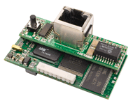 | |
Order reference | NWPM |
item number | 356960 |
Operating conditions | 0 to 55 ° C |
Ethernet interface | RJ45 10BaseT |
protocol | Modbus TCP |
Modbus TCP port | 502 |
Slave ID | 1 |
Storage | 16 MB RAM |
CPU | ARM7 TDMI @ 74MHz clock |
operating system | Linux 2.4.21 |
Usable | from WPM 2004 |
Delivery status with | |
Firmware | A1.5.0 |
user interface | v12 |
System requirement
The minimum system requirement for using the NWPM extension is a Dimplex heat pump with heat pump manager WPM 2004, WPM 2006, WPM 2007 or WPM EconPlus series with software version H_H50 and higher.
Furthermore, a PC with network connection, a router and an S / FTP cable of category 5e or higher is required to connect the NWPM extension necessary. A browser such as Mozilla Firefox must be installed on the PC to display the user-specific interface.
Function codes supported
Type | R / W | Function code | Modbus function |
|---|---|---|---|
Digital | R. | 01 (0x01) | Read coils |
Analogue | R. | 03 (0x03) | Read Holding Register |
Digital | W. | 05 (0x05) | Write single coil |
Analogue | W. | 06 (0x06) | Write single register |
Digital | W. | 15 (0x15) | Write multiple coils |
Analogue | W. | 16 (0x16) | Write multiple registers |
installation
| Note |
|---|
ATTENTION |
The installation of the NWPM extension takes place on the heat pump manager in the designated slot “Serial Card / BMS Card”. The following steps are carried out:
De-energize the heat pump manager

Remove the cover of the “Serial Card / BMS Card” slot with a small screwdriver

Installation of the NWPM extension

Close the opening with the enclosed cover
Supply the heat pump manager with voltage
| Info |
|---|
NOTE |
Heat pump manager settings
Depending on the software version of the heat pump manager, the following settings must be checked and, if necessary, adjusted:
Software version | menu | Submenu | Setting value |
|---|---|---|---|
from WPM_H | Modem -> with the key combination «menu"+"Enter" Select | protocol | Local |
baud rate | 19200 | ||
address | 001 | ||
from WPM_L | Network -> with the key «menu" Select | protocol | LAN |
from WPM_L20.2 | Network -> with the key «menu" Select | protocol | LAN |
Address range | 1..127 |
Determine the IP address
Access to the user interface of the NWPM extension takes place via the dynamically assigned IP address of the router. This IP address can be found in the router's user interface using the respective MAC address of the NWPM extension can be read out. To do this, the administration of the router must be accessed.
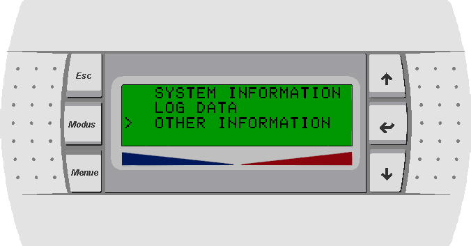
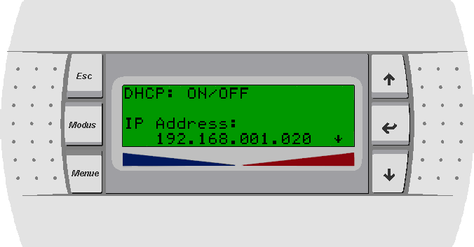
From the heat pump manager software version L12 and firmware version A1.5.0 of the NWPM extension (delivery status from May 2013), the IP address assigned by the router can be read in the menu. This menu is accessed by pressing the key combination at the same time (approx. 5 seconds) «ESC» and «Enter». By pressing the «buttonmenu»You get back to the standard display.
Use the arrow keys to select "OTHER INFORMATION" and use «Enter» confirm
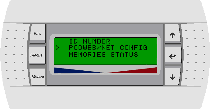
Select "PCOWEB / NET CONFIG" with the arrow keys and press «Enter» confirm
Select "PCOWEB settings" with the arrow keys and press «Enter» confirm
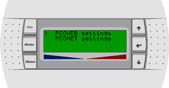
If the NWPM extension is connected to a router where the DHCP function is active, the assigned IP address is displayed
If the NWPM extension is not connected to a router, a fixed IP address can be assigned
The selection of DHCP must be set from ON to OFF and the desired IP address set
The netmask and gateway
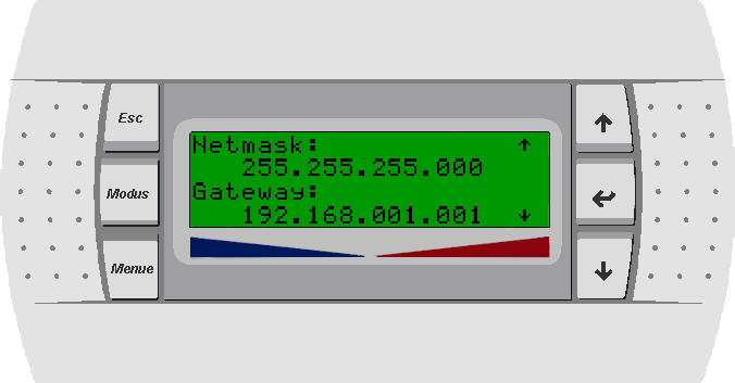
or DNS1 and DNS2 can be read or assigned
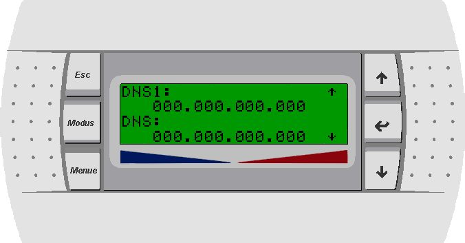
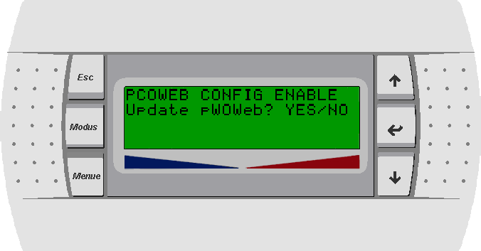
If changes have been made, they must finally be confirmed with YES and a restart carried out
Hostname
After successfully assigning a dynamic IP address to the router and supporting this function, there is the option of access via a host name. This is made up of the term "pcowebXXXXXX" and the last 6 digits of the MAC address.
Example: http: // pcoweb10601f /
| Info |
|---|
NOTE |
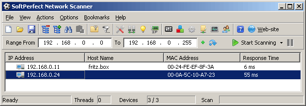
Netscan
First of all, the current version "Netscan" for the existing operating system must be searched for on the Internet and saved on the hard drive. If necessary, the folder content is then extracted and the "netscan.exe" file is executed.
IP address range selection of the network via the "IP" icon

Mark the address range of the network
Scanning the IP addresses "Start Scanning" and reading out the IP address based on the MAC address
Data point list
Operating data
KNX / EIB
Modbus
Modbus
Address | Datapoint type | ||
|---|---|---|---|
IN / OUT
COIL/REG |
|---|
Conversion Rule
Conversion Value
DPT
R/W | Unit | ||
|---|---|---|---|
Surname | WPM software J / L | WPM software H | |
Outside temperature (R1) | 1 | 27 | signed 16 bit |
OUT
register |
None
9.001
signed 16 bit
R.
° C
R | ° C | ||
Return temperature (R2) | 2 | 29 | signed 16 bit |
OUT
register |
None
9.001
signed 16 bit
R |
° C | |||
Return temperature setpoint | 53 | 28 | signed 16 bit |
OUT
register |
None
9.001
R |
° C | |
Hot water temperature (R3) | 3 |
30 | signed 16 bit |
register |
None
signed 16 bit
R |
° C | |||
Set hot water temperature | 58 | 40 | signed 16 bit |
OUT
register |
None
9.001
R |
° C | |||
Flow temperature (R9) | 5 | 31 | signed 16 bit |
OUT
register |
None
9.001
R |
° C | |
Heat source inlet temperature (R24) * |
6 | - | signed 16 bit |
register |
None
signed 16 bit
R |
° C | |
Heat source outlet temperature (R6) |
7 | 41 | signed 16 bit |
OUT
register |
None
9.001
signed 16 bit
R.
R | ° C | ||
Target temperature 2nd heating circuit | 54 | 32 | signed 16 bit |
OUT
register |
None
9.001
signed 16 bit
R |
° C | |||
Temperature 2nd heating circuit (R5) | 9 | 33 | signed 16 bit |
OUT
register |
None
9.001
R |
° C | |||
Target temperature 3rd heating circuit | 55 | 34 | signed 16 bit |
register |
None
signed 16 bit
R |
° C | |||
Temperature 3rd heating circuit (R13) | 10 | 35 | signed 16 bit |
register |
None
signed 16 bit
R |
° C | |
Room temperature 1 / RT-RTH Econ |
11 | 36 | signed 16 bit |
OUT
register |
None
9.001
R |
° C | |
Room temperature 2 |
12 | 38 | signed 16 bit |
register |
None
signed 16 bit
R |
° C | |
Room humidity 1 / RT-RTH Econ |
13 | 37 | unsigned 16 bit |
OUT
register |
None
9.001
unsigned 16 bit
R.
R | ° C |
Room humidity 2 |
14 | 39 | unsigned 16 bit |
register |
None
unsigned 16 bit
R |
° C | ||||||
Passive cooling | ||||||
Flow temperature (R11) | ||||||
19 | 42 | signed 16 bit |
OUT
register |
None
9.001
R |
° C | |
Return temperature (R4) |
20 | 43 | signed 16 bit |
register |
None
signed 16 bit
R |
° C | ||||||
Passive / active cooling | ||||||
Return temp. according to primary circuit (R24) | 21 | - | signed 16 bit | |||
register |
None
signed 16 bit
R |
° C | ||||||
Solar | ||||||
Collector sensor (R23) | 10 | - | signed 16 bit | |||
register |
None
9.001
R |
° C | |||
Solar storage tank (R22) | 23 | - | signed 16 bit |
OUT
register |
None
9.001
R |
° C |
Ventilation | ||||||
Outside air temperature | 120 | - | signed 16 bit | |||
OUT
register |
None
9.001
R |
° C | |||
Supply air temperature | 121 | - | signed 16 bit |
register |
None
signed 16 bit
R |
° C | |||
Exhaust air temperature | 122 | - | signed 16 bit |
register |
None
signed 16 bit
R |
° C | |||
Exhaust air temperature | 123 | - | signed 16 bit |
register |
None
signed 16 bit
R |
° C | |||
Speed of supply air fan | 125 | - | signed 16 bit |
OUT
register |
None
9.001
R |
1 / min | |||
Exhaust fan speed | 126 | - | signed 16 bit |
OUT
register |
9.001
signed 16 bit
R |
1 / min |
| Info |
|---|
*NOTE |
history
KNX / EIB
Modbus
Modbus
Address
Datapoint type
IN / OUT
COIL / REG
Conversion Rule
Conversion Value
Addres | Datapoint type | COIL/REG | R/W | Unit | |
|---|---|---|---|---|---|
Surname | WPM software J / L | WPM software H | |||
Surname
RTU
IP
RTU
IP
Compressor 1 | 72 | 64 | unsigned 16 bit |
OUT
register |
None
R |
hour | |||
Compressor 2 | 73 | 65 | unsigned 16 bit |
OUT
register |
None
R |
hour | |||
Primary pump / fan (M11) | 74 | 66 | unsigned 16 bit |
OUT
register |
7.007
R |
hour | |||
2nd heat generator (E10) | 75 | 67 | unsigned 16 bit |
register |
None
7.007
R |
hour | |||
Heating pump (M13) | 76 | 68 | unsigned 16 bit |
register |
7.007
R |
hour | |||
Hot water pump (M18) | 77 | 69 | unsigned 16 bit |
register |
None
R |
hour | |||
Flange heating (E9) | 78 | 70 | unsigned 16 bit |
register |
None
R |
hour | |||
Swimming pool pump (M19) | 79 | 71 | unsigned 16 bit |
OUT
register |
None
R |
hour | |||
Additional circulation pump (M16) | 71 | - | unsigned 16 bit |
OUT
register
None
register | R |
hour |
Amount of heat* Heating 1-4 |
5096 |
228
5101 | unsigned 16 bit |
register |
None
7.007
R |
kWh | |
Amount of heat* Heating 5-8 |
224
5097 |
5102 | unsigned 16 bit |
register |
None
7.007
R |
kWh | |
Amount of heat* Heating 9-12 |
225
5098 |
5103 | unsigned 16 bit |
register |
None
R |
kWh | |
Amount of heat* Hot water 1-4 |
5099 |
231
5104 | unsigned 16 bit |
register |
7.007
R |
kWh | |
Amount of heat* Hot water 5-8 |
5100 |
232
5105 | unsigned 16 bit |
register |
7.007
R |
kWh | |
Amount of heat* Hot water 9-12 |
5101 |
5106 | unsigned 16 bit |
OUT
register |
7.007
R |
kWh | |
Amount of heat* Swimming pool 1-4 |
5102 |
5107 | unsigned 16 bit |
OUT
register |
None
R |
kWh | |
Amount of heat* Swimming pool 5-8 |
5103 |
5108 | unsigned 16 bit |
register |
None
R |
kWh | |
Amount of heat* Swimming pool 9-12 |
231
5104 |
5109 | unsigned 16 bit |
register |
7.007
R |
kWh |
| Info |
|---|
*NOTE |
Example of heat quantities*
The heat quantities are made up of 3 indices. These 3 indices have to be combined with the following formula for the amount of heat.
Heat amount heating = (heat amount heating 9-12 * 100000000) + (heat amount heating 5-8 * 10000) + heat amount heating 1-4
The amount of heat for "hot water" and "swimming pool" is determined according to this description. However, the corresponding data point is used here.
settings
1st heating circuit
KNX / EIB
Modbus
Modbus
Address | Datapoint type | |
|---|---|---|
COIL/REG |
|---|
Conversion Value
DPT
R/W | Range | Unit | |
|---|---|---|---|
Surname | WPM software J/L | WPM software H | |
Surname
RTU
IP
IP
Min. | Max. | |
|---|---|---|
Parallel shift |
5036 |
5002 | unsigned 16 bit |
register |
7.001
R/W | 0 | 38 | ||||||
0 = -19 | 20 = 1 | |||||||
Room temperature | 46 | 21 | unsigned 16 bit | |||||
IN / OUT
register |
None
R/W | 15.0 | 30.0 | ° C | |
Fixed setpoint temperature |
5037 |
130
5003 |
unsigned 16 bit
IN / OUT
register
None
7.001
R / W
18th
60
° C
Heating curve end point
165
5038
142
unsigned 16 bit |
register |
None
R/W |
18 |
60 | ° C |
Hysteresis
47
Heating curve end point | 5038 | 5015 | unsigned 16 bit |
register |
Divide
7.001
R/W |
0.5
5.0
20 | 70 | ° C |
Hysteresis | 47 |
22 | unsigned 16 bit |
register |
Multiply
10
7.001
R/W | 0.5 | 5.0 | K |
Target temp. dyn. cooling |
170
5043 |
151
5024 | unsigned 16 bit |
IN / OUT
register |
7.001
R/W | 10 | 35 | ° C |
2nd / 3rd heating circuit
In order to be able to make changes to the 2nd or 3rd heating circuit, the changeover must take place via an address. After switching over this address, it is possible to change parameters in the desired heating circuit without any problems.
| Info |
|---|
* ProgrammingNOTE |
KNX / EIB
Modbus | Address | Datapoint type | IN / OUT | COIL / REG | Conversion Rule | Conversion Value | DPT | R / W | Range | Unit | |||
|---|---|---|---|---|---|---|---|---|---|---|---|---|---|
Surname | RTU | IP | Min. | Max. | |||||||||
Select heating circuit 2/3 | 209 | 5082 | Unsigned 16 bit | IN / OUT | register | None | 7.001 | R / W | 2 | 3 | |||
2 = 2nd heating circuit | |||||||||||||
Heating curve end point | 211 | 5084 | Unsigned 16 bit | IN / OUT | register | None | 7.001 | R / W | 20th20 | 70 | ° C | ||
Fixed value temperature | 212 | 5085 | Unsigned 16 bit | IN / OUT | register | None | 7.001 | R / W | 20th20 | 60 | ° C | ||
Parallel shift | 213 | 5086 | Unsigned 16 bit | IN / OUT | register | None | 7.001 | R / W | 0 | 38 | |||
0 = -19 | 20 = 1 | ||||||||||||
Mixer runtime | 214 | 5087 | Unsigned 16 bit | IN / OUT | register | None | 7.001 | R / W | 1 | 6th | Min | ||
Mixer hysteresis | 93 | Unsigned 16 bit | IN | register | Divide | 10 | 7.001 | R / W | 0.5 | 2.0 | K | ||
Mixer hysteresis | 93 | Unsigned 16 bit | OUT | register | Multiply | 10 | 7.001 | R / W | 0.5 | 2.0 | K | ||
Maximum temperature | 215 | 5088 | Unsigned 16 bit | IN / OUT | register | None | 7.001 | R / W | 30th30 | 70 | ° C | ||
Cooling set room temperature | 216 | 5089 | Unsigned 16 bit | IN / OUT | register | None | 7.001 | R / W | 0 | 30th | |||
0 = 15.0 | 16 = 23.0 | ° C | |||||||||||
mode
KNX / EIBModbus | Modbus | ||||||||||||
|---|---|---|---|---|---|---|---|---|---|---|---|---|---|
Address | Datapoint type | IN / OUT | COIL / REG | Conversion Rule | Conversion Value | DPT | R / W | Range | |||||
WPM software J / L | WPM software H | ||||||||||||
Surname | RTU | IP | RTU | IP | Min. | Max. | |||||||
operation mode | 142 | 5015 | 134 | 5007 | Unsigned 16 bit | IN / OUT | register | None | 7.001 | R / W | 0 | 5 | |
0 = summer | |||||||||||||
Number of party hours | 143 | 5016 | 135 | 5008 | Unsigned 16 bit | IN / OUT | register | None | 7.001 | R / W | 0 | 72 | |
Number of vacation days | 144 | 5017 | 136 | 5009 | Unsigned 16 bit | IN / OUT | register | None | 7.001 | R / W | 0 | 150 | |
ventilation | |||||||||||||
stages | 161 | 5034 | - | Unsigned 16 bit | IN / OUT | register | None | 7.001 | R / W | 0 | 5 | ||
0 = off | |||||||||||||
Time value burst ventilation | 127 | - | Unsigned 16 bit | IN / OUT | register | None | 7.001 | R / W | 15th15 | 90 | |||
| Info |
|---|
NOTE |
Hot water
KNX / EIBModbus | Modbus | |||||||||||||
|---|---|---|---|---|---|---|---|---|---|---|---|---|---|---|
Address | Datapoint type | IN / OUT | COIL / REG | Conversion Rule | Conversion Value | DPT | R / W | Range | Unit | |||||
WPM software J / L | WPM software H | |||||||||||||
Surname | RTU | IP | RTU | IP | Min. | Max. | ||||||||
Hysteresis | 172 | 5045 | 131 | 5004 | unsigned 16 bit | IN / OUT | register | None | 7.001 | R / W | 2 | 15th15 | K | |
Target temperature | 174 | 5047 | 149 | 5022 | unsigned 16 bit | IN / OUT | register | None | 7.001 | R / W | Temp. Minim. | 85 | ° C | |
Target temperature minimum | 272 | 5145 | - | - | unsigned 16 bit | IN / OUT | register | None | 7.001 | R / W | 10 | Intended toTemp. | ° C | |
Target temperature maximum | 175 | 5048 | - | - | unsigned 16 bit | IN / OUT | register | None | 7.001 | R / W | Intended toTemp. | 85 | ° C | |
swimming pool
KNX / EIBModbus | Modbus | |||||||||||||
|---|---|---|---|---|---|---|---|---|---|---|---|---|---|---|
Address | Datapoint type | IN / OUT | COIL / REG | Conversion Rule | Conversion Value | DPT | R / W | Range | Unit | |||||
WPM software J / L | WPM software H | |||||||||||||
Surname | RTU | IP | RTU | IP | Min. | Max. | ||||||||
Hysteresis | 176 | 5049 | - | unsigned 16 bit | IN / OUT | register | None | 7.001 | R / W | 1 | 20th20 | K | ||
Target temperature | 178 | 5051 | - | unsigned 16 bit | IN / OUT | register | None | 7.001 | R / W | 5 | 60 | ° C | ||
2. Heat generator
KNX / EIBModbus | Modbus | |||||||||||||
|---|---|---|---|---|---|---|---|---|---|---|---|---|---|---|
Address | Datapoint type | IN / OUT | COIL / REG | Conversion Rule | Conversion Value | DPT | R / W | Range | Unit | |||||
WPM software J / L | WPM software H | |||||||||||||
Surname | RTU | IP | RTU | IP | Min. | Max. | ||||||||
Mixer hysteresis | 48 | 20th20 | unsigned 16 bit | IN | register | Divide | 10 | 7.001 | R / W | 0.5 | 2.0 | K | ||
Mixer hysteresis | 48 | 20th20 | unsigned 16 bit | OUT | register | Multiply | 10 | 7.001 | 0.5 | 2.0 | K | |||
Limit temperature parallel | 147 | 5020 | 19th19 | unsigned 16 bit | IN / OUT | register | None | 7.001 | R / W | -25 | 35 | ° C | ||
Mixer runtime | 148 | 5021 | 37 | unsigned 16 bit | IN / OUT | register | None | 7.001 | R / W | 30th30 | 85 | Min | ||
Selection of time functions
Access to the time functions, e.g. for blocking, lowering / increasing values or times, is achieved by switching over the address 192 (Modbus IP 5065).
| Info |
|---|
* ProgrammingNOTE |
Lowering / raising
KNX / EIB | Modbus | Modbus | |||||||||||||||||
|---|---|---|---|---|---|---|---|---|---|---|---|---|---|---|---|---|---|---|---|
Address | Datapoint type | IN / OUT | COIL / REG | Conversion Rule | Conversion Value | DPT | R / W | Range | |||||||||||
Surname | RTU | IP | Min. | Max. | |||||||||||||||
1st heating circuit | |||||||||||||||||||
Subsidence | 192 | 5065 | Unsigned 16 bit | IN / OUT | register | None | 7.001 | R / W | 1 | 1 | |||||||||
Raising | 192 | 5065 | Unsigned 16 bit | IN / OUT | register | None | 7.001 | R / W | 2 | 2 | |||||||||
2nd heating circuit | |||||||||||||||||||
Subsidence | 192 | 5065 | Unsigned 16 bit | IN / OUT | register | None | 7.001 | R / W | 3 | 3 | |||||||||
Raising | 192 | 5065 | Unsigned 16 bit | IN / OUT | register | None | 7.001 | R / W | 4th44th | 4 | |||||||||
3rd heating circuit | |||||||||||||||||||
Subsidence | 192 | 5065 | Unsigned 16 bit | IN / OUT | register | None | 7.001 | R / W | 5 | 5 | |||||||||
Raising | 192 | 5065 | Unsigned 16 bit | IN / OUT | register | None | 7.001 | R / W | 6th66th | 6 | |||||||||
Time function | |||||||||||||||||||
Start hour 1 | 193 | 5066 | Unsigned 16 bit | IN / OUT | register | None | 7.001 | R / W | 0 | 23 | |||||||||
Start minute 1 | 194 | 5067 | Unsigned 16 bit | IN / OUT | register | None | 7.001 | R / W | 0 | 59 | |||||||||
End of hour 1 | 195 | 5068 | Unsigned 16 bit | IN / OUT | register | None | 7.001 | R / W | 0 | 23 | |||||||||
End of minute 1 | 196 | 5069 | Unsigned 16 bit | IN / OUT | register | None | 7.001 | R / W | 0 | 59 | |||||||||
Start hour 2 | 197 | 5070 | Unsigned 16 bit | IN / OUT | register | None | 7.001 | R / W | 0 | 23 | |||||||||
Start minute 2 | 198 | 5071 | Unsigned 16 bit | IN / OUT | register | None | 7.001 | R / W | 0 | 59 | |||||||||
End of lesson 2 | 199 | 5072 | Unsigned 16 bit | IN / OUT | register | None | 7.001 | R / W | 0 | 23 | |||||||||
End of minute 2 | 200 | 5073 | Unsigned 16 bit | IN / OUT | register | None | 7.001 | R / W | 0 | 59 | |||||||||
Sunday | 201 | 5074 | Unsigned 16 bit | IN / OUT | register | None | 7.001 | R / W | 0 | 3 | |||||||||
Monday | 202 | 5075 | Unsigned 16 bit | IN / OUT | register | None | 7.001 | R / W | 0 | 3 | |||||||||
Tuesday | 203 | 5076 | Unsigned 16 bit | IN / OUT | register | None | 7.001 | R / W | 0 | 3 | |||||||||
Wednesday | 204 | 5077 | Unsigned 16 bit | IN / OUT | register | None | 7.001 | R / W | 0 | 3 | |||||||||
Thursday | 205 | 5078 | Unsigned 16 bit | IN / OUT | register | None | 7.001 | R / W | 0 | 3 | |||||||||
Friday | 206 | 5079 | Unsigned 16 bit | IN / OUT | register | None | 7.001 | R / W | 0 | 3 | |||||||||
Saturday | 207 | 5080 | Unsigned 16 bit | IN / OUT | register | None | 7.001 | R / W | 0 | 3 | |||||||||
0 = yes | |||||||||||||||||||
Reduction / increase value | 208 | 5081 | Unsigned 16 bit | IN / OUT | register | None | 7.001 | R / W | 0 | 19th19 | |||||||||
Active time 1 | 125 | Boolean | OUT | Coil | None | 1,001 | R. | 0 | 1 | ||||||||||
Active time 2 | 126 | Boolean | OUT | Coil | None | 1,001 | R. | 0 | 1 | ||||||||||
Hot water lock
KNX / EIB | Modbus | Modbus | |||||||||||||||||
|---|---|---|---|---|---|---|---|---|---|---|---|---|---|---|---|---|---|---|---|
Address | Datapoint type | IN / OUT | COIL / REG | Conversion Rule | Conversion Value | DPT | R / W | Range | |||||||||||
Surname | RTU | IP | Min. | Max. | |||||||||||||||
Hot water lock | 192 | 5065 | Unsigned 16 bit | IN / OUT | register | None | 7.001 | R / W | 7th77th | 7 | |||||||||
Time function | |||||||||||||||||||
Start hour 1 | 193 | 5066 | Unsigned 16 bit | IN / OUT | register | None | 7.001 | R / W | 0 | 23 | |||||||||
Start minute 1 | 194 | 5067 | Unsigned 16 bit | IN / OUT | register | None | 7.001 | R / W | 0 | 59 | |||||||||
End of hour 1 | 195 | 5068 | Unsigned 16 bit | IN / OUT | register | None | 7.001 | R / W | 0 | 23 | |||||||||
End of minute 1 | 196 | 5069 | Unsigned 16 bit | IN / OUT | register | None | 7.001 | R / W | 0 | 59 | |||||||||
Start hour 2 | 197 | 5070 | Unsigned 16 bit | IN / OUT | register | None | 7.001 | R / W | 0 | 23 | |||||||||
Start minute 2 | 198 | 5071 | Unsigned 16 bit | IN / OUT | register | None | 7.001 | R / W | 0 | 59 | |||||||||
End of lesson 2 | 199 | 5072 | Unsigned 16 bit | IN / OUT | register | None | 7.001 | R / W | 0 | 23 | |||||||||
End of minute 2 | 200 | 5073 | Unsigned 16 bit | IN / OUT | register | None | 7.001 | R / W | 0 | 59 | |||||||||
Sunday | 201 | 5074 | Unsigned 16 bit | IN / OUT | register | None | 7.001 | R / W | 0 | 3 | |||||||||
Monday | 202 | 5075 | Unsigned 16 bit | IN / OUT | register | None | 7.001 | R / W | 0 | 3 | |||||||||
Tuesday | 203 | 5076 | Unsigned 16 bit | IN / OUT | register | None | 7.001 | R / W | 0 | 3 | |||||||||
Wednesday | 204 | 5077 | Unsigned 16 bit | IN / OUT | register | None | 7.001 | R / W | 0 | 3 | |||||||||
Thursday | 205 | 5078 | Unsigned 16 bit | IN / OUT | register | None | 7.001 | R / W | 0 | 3 | |||||||||
Friday | 206 | 5079 | Unsigned 16 bit | IN / OUT | register | None | 7.001 | R / W | 0 | 3 | |||||||||
Saturday | 207 | 5080 | Unsigned 16 bit | IN / OUT | register | None | 7.001 | R / W | 0 | 3 | |||||||||
0 = yes | |||||||||||||||||||
Active time 1 | 125 | Boolean | OUT | Coil | None | 1,001 | R. | 0 | 1 | ||||||||||
Active time 2 | 126 | Boolean | OUT | Coil | None | 1,001 | R. | 0 | 1 | ||||||||||
Thermal disinfection
KNX / EIBModbus | Modbus | |||||||||||
|---|---|---|---|---|---|---|---|---|---|---|---|---|
Address | Datapoint type | IN / OUT | COIL / REG | Conversion Rule | Conversion Value | DPT | R / W | Range | Unit | |||
Surname | RTU | IP | Min. | Max. | ||||||||
Thermal disinfection | 192 | 5065 | Unsigned 16 bit | IN / OUT | register | None | 7.001 | R / W | 8th88th | 8 | ||
Time function | ||||||||||||
Start hour | 193 | 5066 | Unsigned 16 bit | IN / OUT | register | None | 7.001 | R / W | 0 | 23 | hour | |
Start minute | 194 | 5067 | Unsigned 16 bit | IN / OUT | register | None | 7.001 | R / W | 0 | 59 | min | |
Sunday | 201 | 5074 | Unsigned 16 bit | IN / OUT | register | None | 7.001 | R / W | 0 | 1 | ||
Monday | 202 | 5075 | Unsigned 16 bit | IN / OUT | register | None | 7.001 | R / W | 0 | 1 | ||
Tuesday | 203 | 5076 | Unsigned 16 bit | IN / OUT | register | None | 7.001 | R / W | 0 | 1 | ||
Wednesday | 204 | 5077 | Unsigned 16 bit | IN / OUT | register | None | 7.001 | R / W | 0 | 1 | ||
Thursday | 205 | 5078 | Unsigned 16 bit | IN / OUT | register | None | 7.001 | R / W | 0 | 1 | ||
Friday | 206 | 5079 | Unsigned 16 bit | IN / OUT | register | None | 7.001 | R / W | 0 | 1 | ||
Saturday | 207 | 5080 | Unsigned 16 bit | IN / OUT | register | None | 7.001 | R / W | 0 | 1 | ||
0 = yes | ||||||||||||
temperature | 208 | 5081 | unsigned 16 bit | IN / OUT | register | None | 7.001 | R / W | 60 | 85 | ° C | |
active | 125 | boolean | OUT | Coil | None | 1,001 | R. | 0 | 1 | no | ||
DHW circulation pump
KNX / EIB | |||||||||||
|---|---|---|---|---|---|---|---|---|---|---|---|
Modbus | Modbus | ||||||||||
Address | Datapoint type | IN / OUT | COIL / REG | Conversion Rule | Conversion Value | DPT | R / W | Range | |||
Surname | RTU | IP | Min. | Max. | |||||||
Circulation pump | 192 | 5065 | Unsigned 16 bit | IN / OUT | register | None | 7.001 | R / W | 12th | 12th | |
Time function | |||||||||||
Start hour 1 | 193 | 5066 | Unsigned 16 bit | IN / OUT | register | None | 7.001 | R / W | 0 | 23 | |
Start minute 1 | 194 | 5067 | Unsigned 16 bit | IN / OUT | register | None | 7.001 | R / W | 0 | 59 | |
End of hour 1 | 195 | 5068 | Unsigned 16 bit | IN / OUT | register | None | 7.001 | R / W | 0 | 23 | |
End of minute 1 | 196 | 5069 | Unsigned 16 bit | IN / OUT | register | None | 7.001 | R / W | 0 | 59 | |
Start hour 2 | 197 | 5070 | Unsigned 16 bit | IN / OUT | register | None | 7.001 | R / W | 0 | 23 | |
Start minute 2 | 198 | 5071 | Unsigned 16 bit | IN / OUT | register | None | 7.001 | R / W | 0 | 59 | |
End of lesson 2 | 199 | 5072 | Unsigned 16 bit | IN / OUT | register | None | 7.001 | R / W | 0 | 23 | |
End of minute 2 | 200 | 5073 | Unsigned 16 bit | IN / OUT | register | None | 7.001 | R / W | 0 | 59 | |
Sunday | 201 | 5074 | Unsigned 16 bit | IN / OUT | register | None | 7.001 | R / W | 0 | 3 | |
Monday | 202 | 5075 | Unsigned 16 bit | IN / OUT | register | None | 7.001 | R / W | 0 | 3 | |
Tuesday | 203 | 5076 | Unsigned 16 bit | IN / OUT | register | None | 7.001 | R / W | 0 | 3 | |
Wednesday | 204 | 5077 | Unsigned 16 bit | IN / OUT | register | None | 7.001 | R / W | 0 | 3 | |
Thursday | 205 | 5078 | Unsigned 16 bit | IN / OUT | register | None | 7.001 | R / W | 0 | 3 | |
Friday | 206 | 5079 | Unsigned 16 bit | IN / OUT | register | None | 7.001 | R / W | 0 | 3 | |
Saturday | 207 | 5080 | Unsigned 16 bit | IN / OUT | register | None | 7.001 | R / W | 0 | 3 | |
0 = yes | |||||||||||
Active time 1 | 125 | Boolean | OUT | Coil | None | 1,001 | R. | 0 | 1 | ||
Active time 2 | 126 | Boolean | OUT | Coil | None | 1,001 | R. | 0 | 1 | ||
Display ads
KNX / EIB | ||||||||||||
|---|---|---|---|---|---|---|---|---|---|---|---|---|
Modbus | Modbus | |||||||||||
Address | Datapoint type | IN / OUT | COIL / REG | Conversion Rule | Conversion Value | DPT | R / W | Range | ||||
Surname | WPM software L | WPM software J | WPM software H | Min. | Max. | |||||||
103 | 43 | 14th | unsigned 16 bit | OUT | register | None | 7.001 | R. | 0 | 30th | ||
104 | 59 | 94 | unsigned 16 bit | OUT | register | None | 7.001 | R. | 1 | 42 | ||
105 | 42 | 13th | unsigned 16 bit | OUT | register | None | 7.001 | R. | 1 | 31 | ||
106 | - | - | unsigned 16 bit | OUT | register | None | 7.001 | R. | 1 | 27 | ||
Status reports
Value | Description | ||
|---|---|---|---|
L software | H / J software | ||
0 | the endOffthe end | Off | |
1 | the end | Heat pump on heatingOff | Heating |
2 | Heat | Heat pump on heatingHeating | Heating |
3 | swimming Swimming poolHeat pump | A swimming Swimming pool | |
4th4 | Hot Domestic hot water | Heat pump One Domestic hot water | |
5 | CoolCooling | Heat pump One heating + 2nd heat generator | |
6th6 | Heat pump A swimming pool + 2nd heat generator | ||
7th7 | Heat pump One hot water + 2nd heat generator | ||
8th8 | Primary pump supply | ||
9 | Heating rinse | ||
10 | Defrost | ||
11th11 | Flow monitoring | Lower limit of use | |
12th12 | Low pressure limit | ||
13th13 | Low pressure shutdown | ||
14th14 | High pressure protection | ||
15th15 | Switching cycle lock | ||
16 | Minimum service life | ||
17th17 | Network load | ||
18th18 | Flow monitoring | ||
19th19 | 2. Heat generator | ||
20th20 | Low pressure brine | ||
21 | Heat pump on defrost | ||
22nd22 | Upper limit of use | ||
23 | External lock | ||
24 | Operating mode switchover delay | Operating mode cooling | |
25th25 | Frost protection cold | ||
26th26 | Lead limit | ||
27 | Dew point monitor | ||
28 | dew point | ||
29 | Passive cooling | ||
30th30 | |||
Lock
Value | Description | ||
|---|---|---|---|
L software | J software | H software | |
0 | |||
1 | Application limit HT | Outside temperature | |
2 | Volume flow | Application limit WP | Bivalent alternative |
3 | Regenerative | Bivalent regenerative | |
4th4 | Rewind | ||
5 | Function control | Hot water reheating | Hot water |
6th6 | Application limit HT | System control | System control |
7th7 | System control | EVU lock | EVU lock |
8th8 | Cooling switchover delay | ||
9 | Pump feed | High pressure | |
10 | Minimum service life | Low pressure | |
11th11 | Network load | Flow | |
12th | Switching cycle lock | Soft starter | |
13th | Hot water reheating | ||
14th | Regenerative | ||
15th | EVU lock | ||
16 | Soft starter | ||
17th | Flow | ||
18th | Application limit heat pump | ||
19th | High pressure | ||
20th | Low pressure | ||
21 | Application limit heat source | ||
23 | System limit | ||
24 | Load primary circuit | ||
25th | External lock | ||
33 | EvD initialization | ||
34 | 2. Heat generator released | ||
35 | |||
36 | Pump feed | ||
37 | Minimum service life | ||
38 | Network load | ||
39 | Switching cycle lock | ||
40 | Application limit heat source | ||
41 | External lock | ||
42 | 2. Heat generator | ||
43 | |||
Fault messages
Value | Description | |
|---|---|---|
L software | H / J software | |
0 | no mistake | no mistake |
1 | Error N17.1 | |
2 | Error N17.2 | |
3 | Error N17.3 | Load compressor |
4th4 | Error N17.4 | Coding |
5 | Low pressure | |
6th6 | Electronic Ex valve | Antifreeze |
7th7 | Outside sensor short circuit or break | |
8th8 | Return sensor short circuit or break | |
9 | Hot water sensor short circuit or break | |
10 | WPIO | Frost protection sensor short circuit or break |
11th11 | 2nd heating circuit sensor short circuit or break | |
12th12 | Inverter | Freeze protection sensor short circuit or break |
13th13 | WQIF | Low pressure brine |
14th14 | Motor protection primary | |
15th15 | Flow | |
16 | Low pressure brine | Hot water |
17th17 | High pressure | |
19th19 | ! Primary circuit | Hot gas thermostat |
20th20 | ! Defrost | Application limit cooling |
21 | ! Low pressure brine | |
22nd22 | ! Hot water | |
23 | ! Load compressor | Temperature difference |
24 | ! Coding | |
25th25 | ! Low pressure | |
26th26 | ! Frost protection | |
28 | ! High pressure | |
29 | ! Temperature difference | |
30th30 | ! Hot gas thermostat | |
31 | ! Flow | |
Sensors
Value | Description |
|---|---|
L software | |
1 | Outside sensor (R1) |
2 | Return sensor (R2) |
3 | Hot water sensor (R3) |
4th4 | Coding (R7) |
5 | Flow sensor (R9) |
6th6 | 2nd heating circuit sensor (R5) |
7th7 | 3rd heating circuit sensor (R13) |
8th8 | Regenerative sensor (R13) |
9 | Room sensor 1 |
10 | Room sensor 2 |
11th11 | Heat source outlet sensor (R6) |
12th12 | Heat source inlet sensor (R24) * |
14th14 | Collector sensor (R23) |
15th15 | Low pressure sensor (R25) |
16 | High pressure sensor (R26) |
17th17 | Room humidity 1 |
18th18 | Room humidity 2 |
19th19 | Frost protection cold sensor |
20th20 | Hot gas |
21 | Return sensor (R2.1) |
22nd22 | Swimming pool sensor (R20) |
23 | Flow sensor cooling passive (R11) |
24 | Return flow sensor cooling passive (R4) |
26th26 | Solar cylinder sensor (R22) |
28 | Demand sensor for heating (R2.2) |
29 | RTM Econ |
30th30 | Demand sensor cooling (R39) |
| Info |
|---|
*NOTE |
Entrances
Surname | Address | Datapoint type | Functions | R / W | Range | Unit | |
|---|---|---|---|---|---|---|---|
Min. | Max. | ||||||
Photovoltaic feed | 1 | Unsigned 16 bit | 0x04 | R. | 0 | 1 | no |
0 = no | |||||||
Compressor (M1) | 15th | Unsigned 16 bit | 0x04 | R. | 0 | 1 | no |
Flange heating (E9) | 16 | Unsigned 16 bit | 0x04 | R. | 0 | 1 | no |
Solar pump (M23) | 17th | Unsigned 16 bit | 0x04 | R. | 0 | 1 | no |
0 = off | |||||||
| Info |
|---|
NOTE |
Outputs
KNX / EIB | Modbus | Modbus | |||||||||||||||
|---|---|---|---|---|---|---|---|---|---|---|---|---|---|---|---|---|---|
Address | Datapoint type | IN / OUT | COIL / REG | Conversion Rule | Conversion Value | DPT | R / W | ||||||||||
Surname | WPM software J / L | WPM software H | |||||||||||||||
Compressor 1 | 41 | 80 | Boolean | OUT | Coil | None | 1,001 | R. | |||||||||
Compressor 2 | 42 | 81 | Boolean | OUT | Coil | None | 1,001 | R. | |||||||||
Primary pump (M11) / fan (M2) | 43 | 82 | Boolean | OUT | Coil | None | 1,001 | R. | |||||||||
2nd heat generator (E10) | 44 | 83 | Boolean | OUT | Coil | None | 1,001 | R. | |||||||||
Heating pump (M13) | 45 | 84 | Boolean | OUT | Coil | None | 1,001 | R. | |||||||||
Hot water pump (M18) | 46 | 85 | Boolean | OUT | Coil | None | 1,001 | R. | |||||||||
Mixer (M21) open | 47 | 86 | Boolean | OUT | Coil | None | 1,001 | R. | |||||||||
Mixer (M21) CLOSED | 48 | 87 | Boolean | OUT | Coil | None | 1,001 | R. | |||||||||
Additional circulation pump (M16) | 49 | 88 | Boolean | OUT | Coil | None | 1,001 | R. | |||||||||
Flange heating (E9) | 50 | 89 | Boolean | OUT | Coil | None | 1,001 | R. | |||||||||
Heating pump (M15) | 51 | 90 | Boolean | OUT | Coil | None | 1,001 | R. | |||||||||
Mixer (M22) open | 52 | 91 | Boolean | OUT | Coil | None | 1,001 | R. | |||||||||
Mixer (M22) closed | 53 | 92 | Boolean | OUT | Coil | None | 1,001 | R. | |||||||||
Swimming pool pump (M19) | 56 | 95 | Boolean | OUT | Coil | None | 1,001 | R. | |||||||||
Collective fault message (H5) | 57 | - | Boolean | OUT | Coil | None | 1,001 | R. | |||||||||
Heating pump (M14) | 59 | 94 | Boolean | OUT | Coil | None | 1,001 | R. | |||||||||
Cooling pump (M17) | 60 | 99 | Boolean | OUT | Coil | None | 1,001 | R. | |||||||||
Heating pump (M20) | 61 | - | Boolean | OUT | Coil | None | 1,001 | R. | |||||||||
Changeover room thermostats heating / cooling (N9) | 66 | 96 | Boolean | OUT | Coil | None | 1,001 | R. | |||||||||
Primary pump cooling (M12) | 68 | 98 | Boolean | OUT | Coil | None | 1,001 | R. | |||||||||
Solar pump (M23) | 71 | - | Boolean | OUT | Coil | None | 1,001 | R. | |||||||||
| Info |
|---|
NOTE |
Time alignment
Using the time synchronization, it is possible to write the current date and time via the interface. So that the change is accepted by the heat pump manager, the value 1 must be written to the associated "set register" immediately after the time has been written. Only then will the change be applied. The value of the "set register" is automatically reset to the value 0 after writing.
KNX / EIBModbus | Modbus | ||||||||||
|---|---|---|---|---|---|---|---|---|---|---|---|
Address | Datapoint type | IN / OUT | COIL / REG | Conversion Rule | Conversion Value | DPT | R / W | Range | |||
Surname | RTU | IP | Min. | Max. | |||||||
hour | 133 | 5006 | Unsigned 16 bit | IN / OUT | register | None | 7.001 | R / W | 0 | 23 | |
set hour | 102 | Boolean | IN | Coil | None | 1,001 | W. | ||||
minute | 134 | 5007 | Unsigned 16 bit | IN / OUT | register | None | 7.001 | R / W | 0 | 59 | |
set minute | 103 | Boolean | IN | Coil | None | 1,001 | W. | ||||
month | 135 | 5008 | Unsigned 16 bit | IN / OUT | register | None | 7.001 | R / W | 1 | 12th | |
set month | 105 | Boolean | IN | Coil | None | 1,001 | W. | ||||
weekday | 136 | 5009 | Unsigned 16 bit | IN / OUT | register | None | 7.001 | R / W | 1 | 7th | |
1 = Monday | |||||||||||
set day of the week | 107 | Boolean | IN | Coil | None | 1,001 | W. | ||||
Day | 137 | 5010 | Unsigned 16 bit | IN / OUT | register | None | 7.001 | R / W | 1 | 31 | |
set day | 104 | Boolean | IN | Coil | None | 1,001 | W. | ||||
year | 138 | 5011 | Unsigned 16 bit | IN / OUT | register | None | 7.001 | R / W | 0 | 99 | |
set year | 106 | Boolean | IN | Coil | None | 1,001 | W. | ||||
| Info |
|---|
*NOTE |
Function descriptions
In this chapter, some functional descriptions, their implementation and recommendations are collected and explained.
Room temperature control Smart-RTC +
From software version WPM_L23.1 it is possible to use the function of the intelligent room temperature control Smart-RTC + via the BMS interface available on the heat pump manager with the Modbus TCP protocol.
The values of the room temperature, the room humidity (for cooling) and the target room temperature of a maximum of 10 rooms must be sent to the heat pump manager via Modbus TCP. The heat pump manager uses these values to calculate the maximum system temperature required for heating and the minimum possible system temperature for silent cooling, taking the dew point into account.
Necessary settings on the heat pump manager
To use the BMS interface for the intelligent room temperature control Smart-RTC +, additional settings must be made or adjusted on the heat pump manager.
Software version | Pre-configuration menu | Submenu | Setting value |
|---|---|---|---|
from WPM_L23.1 | with the key combination «menu"+"ESC" Select | 1st heating circuit | Heating or heating / silent cooling |
1st heating / cooling circuit heating control via | Room temperature | ||
1. Heating / cooling circuit heating room control | BMS | ||
1. Heating / cooling circuit cooling room control | BMS | ||
1. Heating / cooling circuit Number of room controls | 01-10 |
When using an additional 2nd heating or heating / cooling circuit, the settings must be made in the same way as for the 1st heating circuit.
Software version | Pre-configuration menu | Submenu | Setting value |
|---|---|---|---|
from WPM_L23.1 | with the key combination «menu"+"ESC" Select | 2nd heating circuit | Heating or heating / silent cooling |
2nd heating / cooling circuit heating control via | Room temperature | ||
2. Heating / cooling circuit heating room control | BMS | ||
2. Heating / cooling circuit cooling room control | BMS | ||
2nd heating / cooling circuit number of room controls | 01-10 |
| Note |
|---|
IMPORTANT |
Room control data points
Since only a limited number of addresses are available, the time function switch from Chapter is required to write the values for the rooms "Selection of time functions" utilized. The addresses 50 - 59 for the 1st heating / cooling circuit and 60 - 69 for the 2nd heating / cooling circuit are available for access. A switchover takes place via the object DU_ZF_Wert.
Surname | Data point | index | R / W | Range | Unit | |
|---|---|---|---|---|---|---|
Min. | Max. | |||||
Room addresses 1st heating / cooling circuit | DU_ZF_Wert | 5065 | R / W | 50 | 59 | no |
Room addresses 2nd heating / cooling circuit | DU_ZF_Wert | 5065 | R / W | 60 | 69 | no |
Room temperature 50-69 BMS | E_Raum1_T | 11th11 | R / W | 100 | 500 | 0.1 ° C |
Room humidity 50-69 BMS | E_Raum1_Feu | 13th13 | R / W | 200 | 900 | 0.1% |
Set room temperature 50-69 BMS | P_Raum_Soll | 5081 | R / W | 100 | 300 | 0.1 ° C |
Room clearance 50-69 BMS | Raum_Frei_HzK | 5164 | R / W | 1 | 3 | no |
1 = heating (cooling blocked) | ||||||
Example for writing the room values
The following table relates to the group addresses in the sample project.
Surname | e.g. Group Address |
|---|---|
Read number of rooms | 14/5/1 (sensor) |
Switch room address 50 - 59 | 14/5/2 (actuator) |
Write actual room temperature RIT addr. 50 - 59 | 14/5/4 (actuator) |
Write actual room humidity RIF addr. 50 - 59 | 14/5/6 (actuator) |
Write room target temperature RST addr. 50 - 59 | 14/5/8 (actuator) |
Write room release RFG addr. 50 - 59 | 14/5/10 (actuator) |
The address (14/5/2) is switched over to transfer the room values. The following description is intended to represent one possibility of such an implementation. The room values are written to the heat pump manager every 1 minute per room. With 10 rooms, this means a maximum processing time of 10 minutes. This lead time is not a problem with the small changes in room values and will not limit comfort.
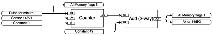
Module 1 - Switching the room addresses
In module 1, a counter is first created which counts up by +1 every minute (pulse for minute). The count starts at 50 and ends with the number of room controllers set (sensor 14/5/1). After the number of set room controllers has been reached, counting starts again at address 50. This count value is written to actuator 14/5/2 every minute. At the same time, marker 1 (AI memory flags 1) is also filled with the counter value. Flag 3 (AI memory flags 3) triggered with the minute pulse. Both flags are required in module 2. The input M with the constant 0 means that the counter starts again at 50 when the number of set room controllers is reached and does not stop when the set room controllers are reached.
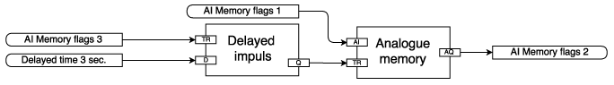
Module 2 - Delayed writing of the room values
After switching the room addresses with module 1, the writing of the values via actuators 14/5/4 (room temperature), 14/5/6 (room humidity), 14/5/8 (target room temperature) and 14 / is delayed by 3 seconds. 5/10 (room clearance). For this, marker 1 (AI memory flags 1) and marker 3 (AI memory flags 3) from step 1 are required. First, a delayed pulse by 3 seconds (delayed time 3 sec.) Is filled via marker 3 (AI memory flags 3). The delayed pulse triggers the analogue memory, which is already filled with marker 1 (AI memory flags 1) count value from module 1. If the delayed pulse is triggered, the value is written from the analogue memory to marker 2 (AI memory flags 2). The value in marker 2 (AI memory flags 2) is still required in module 3.
Module 3 - Compare the room address to be written
The marker 2 (AI memory flags 2) from module 2 contains the current value of the room address that is to be written. So that the correct trigger of the room address is triggered, the room address from marker 2 (AI memory flags 2) must be compared. The marker 2 (AI memory flags 2) is compared with the constant 50 (Constant 50). If the value is the same, another marker 50 (AI memory flags 50) is set. The marker 50 (AI memory flags 50) is required in module 4 and triggers the trigger there.
| Info |
|---|
NOTE |
Module 4 - Writing the room values to the buffer
Module 4 is explained using the example of the target room temperature for room address 50 (Room-set-temperature 50). First, the target room temperature (Room-set-temperature 50) is multiplied by the factor x10. This is necessary because only integers (*) are written. The result is written to an analogue memory. If the marker 50 (AI memory flags 50) is triggered from step 3, the number in the analog memory (analogue memory) is written to the marker RST 50 (AI memory flags RST 50), which in turn simultaneously drives the actuator 14/5 / 8 triggers for the target room temperature.
| Info |
|---|
*NOTE |
| Info |
|---|
NOTE |
Module 5 - Writing the room values to the heat pump manager
Module 5 shows how the room values are triggered in the actuator. It stands
RIT => actual room temperature
RIF => actual room humidity
RST => target room temperature
RFG => room release.
summary
The modules 1 - 5 serve as an example and represent a possibility for the implementation of the description of the room values. The process was deliberately divided into individual modules so that the process can be explained as simply as possible. The modules shown can also be combined, structured differently, or other paths can be selected.
Smart-Grid / SG Ready
The use of photovoltaic electricity ultimately represents a load-variable tariff, since the heat pump can be operated with inexpensive electricity with photovoltaic yield. In this case, a digital input for "green" electricity can be connected on the heat pump manager. In this operating state, the heat pump runs in increased mode for room heating (return target temperature + increase value) and hot water preparation (maximum temperature hot water). The possibility of release via the available interfaces is also given from heat pump manager software version L20.2. The wiring of the digital input is then not required to enable the function.
| Info |
|---|
NOTE |
Operating states
Condition | Address | Description | action | |
|---|---|---|---|---|
3 | 4th | |||
Red | 0 | 1 | In this state, the heat pump runs in reduced mode for space heating and hot water generation. |
|
yellow | 0 | 0 | In this state, the heat pump runs in the set normal mode. | |
green | 1 | 0 | In this state, the heat pump runs in increased mode for space heating and hot water preparation. |
|
| Info |
|---|
*NOTE |
Implementation on the heat pump manager
Address | Datapoint type | IN / OUT | Conversion Rule | Conversion Value | DPT | R / W | Unit | |
|---|---|---|---|---|---|---|---|---|
Surname | WPM software L | |||||||
Operating status "green" | 3 | Boolean | IN / OUT | None | 1,001 | R / W | no | |
Operating status "red" | 4th4 | Boolean | IN / OUT | None | 1,001 | R / W | no |
| Info |
|---|
NOTE |
Contact
For further questions, information and suggestions, please send an email to:
ferndiagnose@gdts.one
with the additional information of:
Device designation
Software version